Wire Gauge for Run Length Calculator
Estimate voltage drop, end voltage, circular mil area, and a practical AWG recommendation for 120 V and 240 V home circuit planning.
▶Circuit Presets
Choose a common branch-circuit scenario or enter the actual voltage, amperage, distance, conductor material, and drop target below.
⚙Wire Run Inputs
Wire Gauge Result
Calculation Breakdown
📐Formula And Conductor Data
| Formula item | Meaning | Value or source | Calculator use |
|---|---|---|---|
| V = 2 × K × I × D / cmils | Single-phase voltage drop | Volts | D is one-way distance; 2 accounts for out and back conductors. |
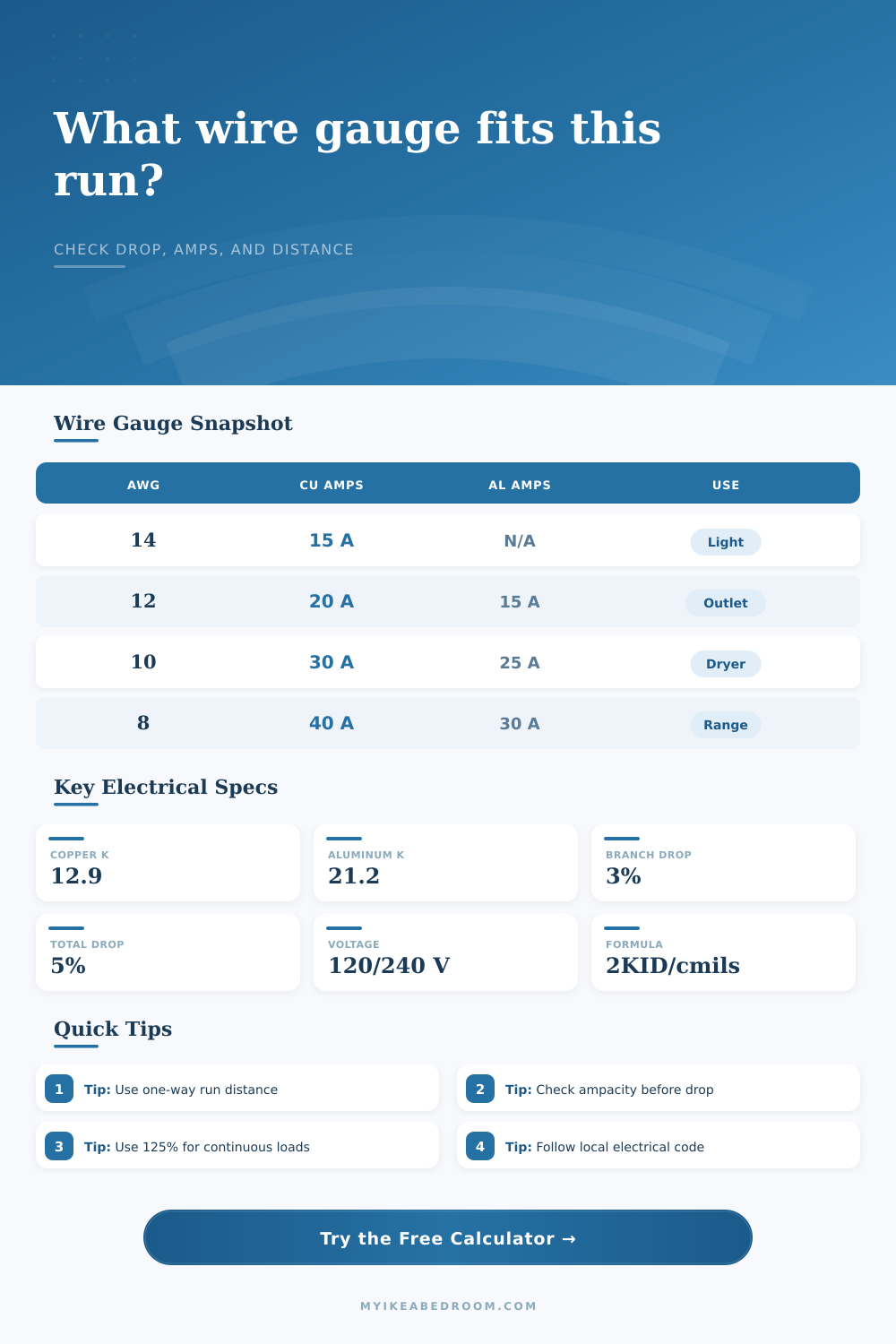
| K for copper | Ohm-cmil per foot | 12.9 | Lower resistance, less voltage drop for the same AWG. |
| K for aluminum | Ohm-cmil per foot | 21.2 | Higher resistance, so larger AWG may be needed for long runs. |
| Drop percent | Voltage lost as percent | Drop V / circuit V | Compared with 3% or 5% planning target. |
| Wire gauge | Circular mils | Copper reference | Aluminum reference |
|---|---|---|---|
| 14 AWG | 4,110 cmils | 15 A small-conductor branch reference | Not a typical aluminum branch-circuit reference |
| 12 AWG | 6,530 cmils | 20 A small-conductor branch reference | 15 A small-conductor branch reference |
| 10 AWG | 10,380 cmils | 30 A small-conductor branch reference | 25 A small-conductor branch reference |
| 8 AWG | 16,510 cmils | 40 A at 60C reference column | 30 A at 60C reference column |
| 6 AWG | 26,240 cmils | 55 A at 60C reference column | 40 A at 60C reference column |
📊Drop Target Tables
| Wire gauge | 120 V at 3% | 120 V at 5% | 240 V at 3% |
|---|---|---|---|
| 14 AWG | 45 ft | 75 ft | 91 ft |
| 12 AWG | 76 ft | 127 ft | 152 ft |
| 10 AWG | 121 ft | 201 ft | 241 ft |
| 8 AWG | 192 ft | 320 ft | 384 ft |
| 6 AWG | 305 ft | 508 ft | 610 ft |
| Circuit example | Voltage | Typical current | Drop target note |
|---|---|---|---|
| Bedroom lighting branch | 120 V | 5 to 10 A | 3% helps keep dimmers and LEDs stable on long runs. |
| General receptacle branch | 120 V | 12 to 16 A | 3% is a practical branch-circuit planning target. |
| Laundry or dryer branch | 240 V | 20 to 30 A | 240 V circuits tolerate more volts lost for the same percent. |
| Garage or workshop feeder | 240 V | 30 to 50 A | Use 5% only as combined feeder plus branch planning guidance. |
| EV charging branch | 240 V | 32 to 48 A | Continuous-load sizing and manufacturer instructions matter. |
| Result area | Good sign | Warning sign | Next check |
|---|---|---|---|
| Voltage drop | At or below target | Above 3% or 5% | Shorten the run, reduce amps, or use larger conductor. |
| End voltage | Near nominal voltage | Low under load | Confirm actual measured load and terminations. |
| Ampacity reference | Adjusted amps pass | Adjusted amps exceed reference | Use code tables, derating, and breaker rules before installing. |
| Suggested gauge | Passes both checks | No listed gauge passes | Move beyond 6 AWG or redesign the circuit path. |
ℹWire Gauge Tips
An electrical circuit is flickering because it’s overworked. It hesitates and this is naturaly because the gauge (thickness) of the electrical wiring in your walls isn’t up to par. Electricity require voltage which is like pressure for water to make it all the way to the upper floors of the home. When there’s not enough pressure at some point, your gadgets has trouble.
You can use the calculator to determine how much pressure you’ll be losing before purchasing the cable. To do this, it consider material resistance, current and distance using a formula. To calculate, you’ll have to input one-way distance from your load (the device receiving power) to your panel. This trips most folks up: they go ahead and put in the total amount of wire; that’s both ways. Don’t worry, the tool does that for you and just needs straight line distance. So if your bathroom fan is sixty feet away, you puts in sixty. The system will multiply that number by two because the hot and neutral conductors is running together. That might not sound like much but doubling the distance mean double the voltage drop.
How to Choose the Right Wire for Your Home
Here again, material selection matter greatly. Aluminum is lighter and less expensive than copper, which is the most commonly used material. However, aluminum has a resistance coefficient of 21.2 compared to copper’s 12.9 in the calculator. That means aluminum will resist electrical current more forcefuly. If you want equivalent voltage drop with aluminum wiring, you’d have to use thicker wire, typically by increasing the gauge size. For that reason, aluminum wiring need special care when terminating and many new houses just stays with copper for their branch circuitry.
It’s always a matter of cost versus performance. There’s also ampacity: how much current can a wire take before it overheats? Voltage drop and heat are separate problems. You could have a wire thick enough to carry the current without melting, but its length might cause an unacceptable voltage loss. This tool accounts for both extremes. It’ll calculate the percentage of voltage lost. Then it will compare your load with established reference tables to see if the wire will melt.
Continuous loads like an EV charger or a heater require more stringent rules. Since the wire remains warm, the calculator multiplies those loads by 125%. Why? This prevents insulation damage after many year of use. Think of it as a safety factor.
So you’ll notice that there are some preset buttons for typical applications such as a garage workshop or a bedroom light. It is not just any old number. It represents actual world draw levels. Five amps is not a lot; it’s what a bedroom light might use. But thirty is a lot if it’s a workshop loaded with grinders and saws. That require a much larger wire to handle the same load. Running too small a wire on a high-draw load is dangerous (fire hazard). Running too large a wire on a low-draw load is wasteful. The trick is finding happy medium.
Most times we use three percent as the voltage drop goal for branch circuits. So it means that from the panel to the outlet you should of not lose more than 3% of the voltage. Now if you are running from one panel to another (a sub-panel) then the combined loss on both the feeder and the branch may go up to five percent. You can look at the tables below to find the max length you can run a given gauge at a certain amperage. This is a quick guide to help you determine if what you want to do is possible with the type of wire you are thinking about using.
Electrical work is unforgiving. No one sees the voltage drop until they can measure it…after the wire has been installed in the wall. Run a little extra to plan for problems later or chase down flickering light after the fact? Plan ahead. The tool provides data to help you decide with confidence. There’s no guessing; there’s a clear answer. Run the correct wire and those lights will shine bright.