Lead-wire planning for headboards, shelves, wardrobes, vanities, and ceiling coves
LED Strip Voltage Drop Calculator
Estimate how much voltage your supply cable loses before power reaches the strip, then compare a thicker wire, a shorter lead, and an extra feed leg without switching to a side-by-side layout.
Each preset loads a real bedroom or media-space layout so a short floating shelf and a full tray ceiling cove do not get the same cable assumptions.
Inputs stay in their own row block. Results appear only below this form so the calculator never uses a split input-and-result layout.
These cards give fast design anchors before you compare a chosen cable against the detailed tables below.
| Wire Gauge | Area | Ohms / 1000 ft | Typical LED use |
|---|---|---|---|
| 22 AWG | 0.33 mm2 | 16.14 | Short 5V leads and signal-adjacent power |
| 20 AWG | 0.52 mm2 | 10.15 | Small shelf accents and mirror loops |
| 18 AWG | 0.82 mm2 | 6.385 | Most 12V and 24V bedroom strips |
| 16 AWG | 1.31 mm2 | 4.016 | Longer 24V feeds and RGBW runs |
| 14 AWG | 2.08 mm2 | 2.525 | High-load vanity and media walls |
| 12 AWG | 3.31 mm2 | 1.588 | Large coves and grouped feed trunks |
| 10 AWG | 5.26 mm2 | 0.999 | Very long trunks before branch splits |
| System | Use case | Ideal target | Maximum target |
|---|---|---|---|
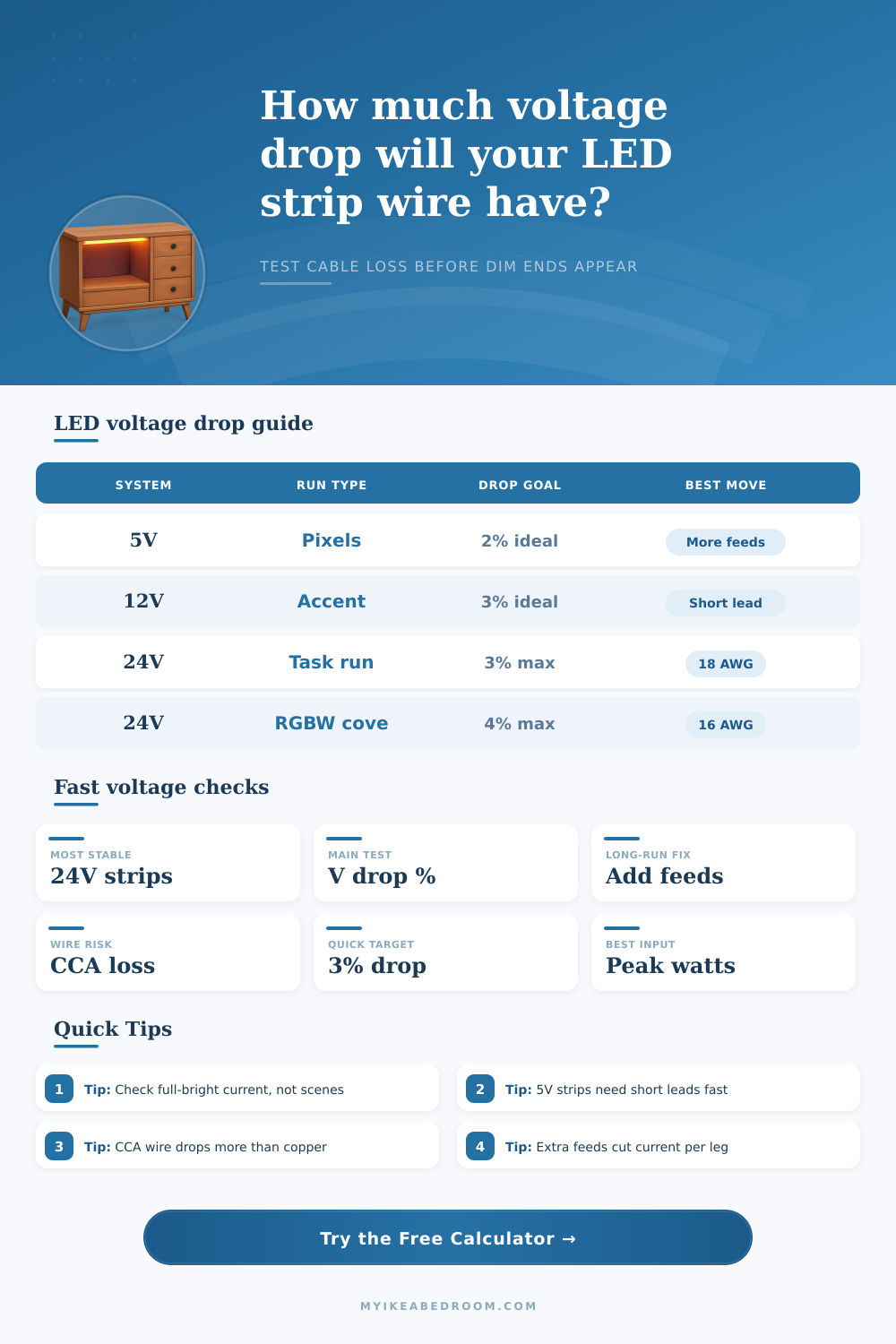
| 5 V | Addressable pixels, low-voltage effects | 1% to 2% | 3% |
| 12 V | Headboards, beds, vanity trim | 2% to 3% | 4% |
| 24 V | Shelves, wardrobes, under-cabinet, task light | 2% to 3% | 4% |
| 24 V RGBW | Room coves, closet color loops | 3% | 4% |
| 48 V | Long trunk feeds to local injectors | 1% to 2% | 3% |
| Family | Voltage | Default density | Typical room location |
|---|---|---|---|
| 5V pixel tape | 5 V | 4.8 W/ft | Effects shelving and programmable scenes |
| 12V accent white | 12 V | 2.4 W/ft | Headboards and under-bed glow |
| 12V dense white | 12 V | 3.0 W/ft | Vanity borders and wardrobe faces |
| 24V task white | 24 V | 3.1 W/ft | Shelves, desk backs, and under-cabinet |
| 24V cove white | 24 V | 3.6 W/ft | Ceiling tray and perimeter wash |
| 24V RGB | 24 V | 4.4 W/ft | Media walls and dynamic accents |
| 24V RGBW | 24 V | 5.8 W/ft | Closets and premium coves |
| Scenario | One-way cable | Feed legs | Starting point |
|---|---|---|---|
| Short shelf wash | 6 to 8 ft | 1 | 18 AWG copper at 12V or 24V |
| Headboard or vanity loop | 8 to 12 ft | 1 to 2 | 18 AWG, then check 16 AWG if dense |
| Media wall cove | 12 to 16 ft | 2 | 16 AWG copper, split load evenly |
| Tray ceiling perimeter | 16 to 20 ft | 2 to 3 | 16 AWG or 14 AWG depending on watts |
| Large RGBW closet loop | 18 to 24 ft | 3 to 4 | 16 AWG minimum with extra injection |
This grid compares four practical next moves using the same load assumptions from your current inputs.
Voltage drop is an phenomenon in which the voltage decrease as the electricity travels through the wire or LED strip. Voltage drop occur because the wire have resistance in them which cause the electricity to lose energy as it travels through the wire. As a result, the LED at the end of the LED strip will be dimmer then those at the beginning of the LED strip.
Furthermore, if the voltage drop is significant, the color of the LEDs may also change or appear to have a differ color temperature than the rest of the strip. You can prevent voltage drop by manage the way in which you provide power to your LED strip. Voltage drop occurs when the electron that carry the electricity must push through the resistance of the wires.
Voltage Drop in LED Strips and How to Fix It
The longer the wire, the more voltage drop will occur. Likewise, if you employ a heavy electrical load, there will be more voltage drop than if you use an light electrical load. The type of wire that you use will affect the amount of voltage drop that you experience.
Pure copper wire have less resistance than copper clad aluminum wires. Therefore, the use of a pure copper wire will cause less voltage drop than if you employ a copper clad aluminum wire. People often use copper clad aluminum wires because they are less expensive.
However, because aluminum has a higher resistance than copper, it will cause more voltage drop. Additionally, the gauge of the wire will also determine the amount of voltage drop that you experience. If your wire is thicker (16 AWG), it will have less resistance than thin wires (22 AWG).
Therefore, if you are using long LED strips, use thicker wires to reduce voltage drop. Additionally, there are different injection method that you can use to avoid voltage drop. For instance, you can provide power to only one end of the LED strip.
However, this will result in voltage drop at the end of the strip. An alternative method is to provide power to both the beginning and end of the LED strip. By provide power to both ends, you reduce the amount of electricity that has to travel through the wire.
An additional injection method is to provide power to the center of the LED strip. By providing power to the center, each end of the LED strip will emit the same amount of light. Finally, another method is to provide extra power feed to the LED strip.
By adding extra power feeds, you divide the electricity so that each wire that carry the electricity contains less current. The voltage of the system will also impact the amount of voltage drop that you experience in your installation. For instance, a 24 volt system will allow electricity to travel further down the LED strip with less voltage drop than a 12 volt system.
A 5 volt system is very sensitive to voltage drop. For example, if you use a 5 volt system with thin wire, the LEDs will flicker or emit little light due to the high rate of voltage drop that exist within a 5 volt system. These LEDs will not be able to emit their full brightness over long distance.
Another consideration is the electrical load that is placed into the LED strip. Many people plan for the average brightness of the LED strip. However, voltage drop is experienced at the maximum brightness level of the LED strip.
For example, if you use an RGBW LED strip, the voltage drop will be highest when all of the color light are on at the same time. Therefore, you should calculate the gauge of the wire based off the maximum brightness and power consumption of the LED strip so that the LEDs will remain bright to their maximum brightness. Another consideration is heat.
Heat will increase the resistance of the wire. The more resistance in the wire, the more the voltage drop. If you bundle too many wire together in the same location, the wires will become hot.
These hot wires will create voltage drop in the LED strip. Additionally, the copper trace that are included in the LED strip have resistance so the LED strip will experience a voltage drop from one end to the other. To ensure your LED strip perform as you intend it to perform:
First, determine the length of the strip and the wattage of the strip.
Second, determine the voltage of the system (for instance 12 or 24 volts). Third, determine the gauge of the wire that will be used in the installation. Fourth, determine from which ends of the strip the power will be injected into the strip.
Finally, measure the actual power that the LEDs will use to ensure that all calculation are accurate. By following these steps and managing your LED strip according to these factor, you can prevent voltage drop from the LED strip. By preventing voltage drop, your LED strip will emit even light from the beginning of the strip to the end of the strip.