Injection planning for headboards, shelves, closets, media walls, and tray ceilings
LED Strip Power Injection Calculator
Calculate injection points, current per feed, cable voltage drop, and PSU size so long bedroom runs stay even from start to end.
Inputs are in this row only. Results appear below in a separate row, never side by side.
Results are guidance values. Confirm final electrical details with local code and driver ratings.
Suggested one-way feed distance by voltage and strip load
| Voltage | Light load | Medium load | Heavy load | Use case |
|---|---|---|---|---|
| 12V | 3-5 ft | 2-4 ft | 1.5-3 ft | Short accents and mirror borders |
| 24V | 6-10 ft | 5-8 ft | 4-6 ft | Shelves, beds, and wardrobe rails |
| 36V | 8-13 ft | 7-10 ft | 5-8 ft | Long task-light runs |
| 48V | 10-16 ft | 8-12 ft | 6-10 ft | Large tray and media coves |
Wire resistance and practical feed current targets
| Gauge | Ohm / 1000 ft | mm2 | Practical amps | Bedroom note |
|---|---|---|---|---|
| 18 AWG | 6.385 | 0.82 | 2-4 A | Short feeds to low-density strips |
| 16 AWG | 4.016 | 1.31 | 4-6 A | Common cabinet and under-bed feeds |
| 14 AWG | 2.525 | 2.08 | 6-8 A | Good default for medium-long runs |
| 12 AWG | 1.588 | 3.31 | 8-12 A | High output RGBW or long coves |
| 10 AWG | 0.999 | 5.26 | 12-16 A | Main trunk feed before split points |
Injection topology behavior at the same strip load
| Topology | Current split | Typical points | Drop trend | When to choose |
|---|---|---|---|---|
| Single-end | 100% one leg | 1 | Highest drop | Short mono runs under 10 ft |
| Both-end | 55% per side | 2 | Lower drop | Linear strips where both ends are reachable |
| Mid + end | 50% split | 2-3 | Stable center | Long strips with visible center dim risk |
| Multi-zone | 40% per leg | 3+ | Lowest drop | Large coves and RGBW scene systems |
Common bedroom and media setups
| Project | Length | Power density | Base inject plan | Wire start point |
|---|---|---|---|---|
| Queen headboard halo | 12 ft | 3.2 W/ft | Both-end | 16 AWG copper |
| Under-bed comfort glow | 16 ft | 2.8 W/ft | Both-end | 16 AWG copper |
| Wardrobe rail strip | 20 ft | 4.5 W/ft | Mid + end | 14 AWG copper |
| Media cove RGBW | 28 ft | 6.0 W/ft | Multi-zone | 12 AWG copper |
| Tray ceiling perimeter | 32 ft | 5.0 W/ft | Multi-zone | 12 AWG copper |
Power injection is an method of supplying power to LED strips in order to even out the voltage that is supplied to the strips. When you connect an LED strip to only one end, the electricity have to travel through the copper traces to the other end of the strip. Each of these traces has electrical resistance, which cause the voltage to even out along the strip.
Thus, the voltage drops along the strip, leading to some LED lights being dimmer than others, as well as shifts in color along RGB LED strips. Power injection help to even out the voltage along the strip, which fixes this problem. To perform power injection, you must consider the total wattage of the LED strip and it’s voltage.
How to Add Power to LED Strips
For example, a 20-foot strip that draws 5 watts of power per foot of strip will draw 100 watts of power. If the LED strip is 24 volts, it is likely that the voltage will drop along the strip after 8 feet due to the voltage drop caused by the built-in wires of the strip not being able to carry 100 watts of power over long distances. Using a strip with 48 volts, however, will reduce the drop in voltage due to the fact that 48 volts of power use less current to carry the same 100 watts of power.
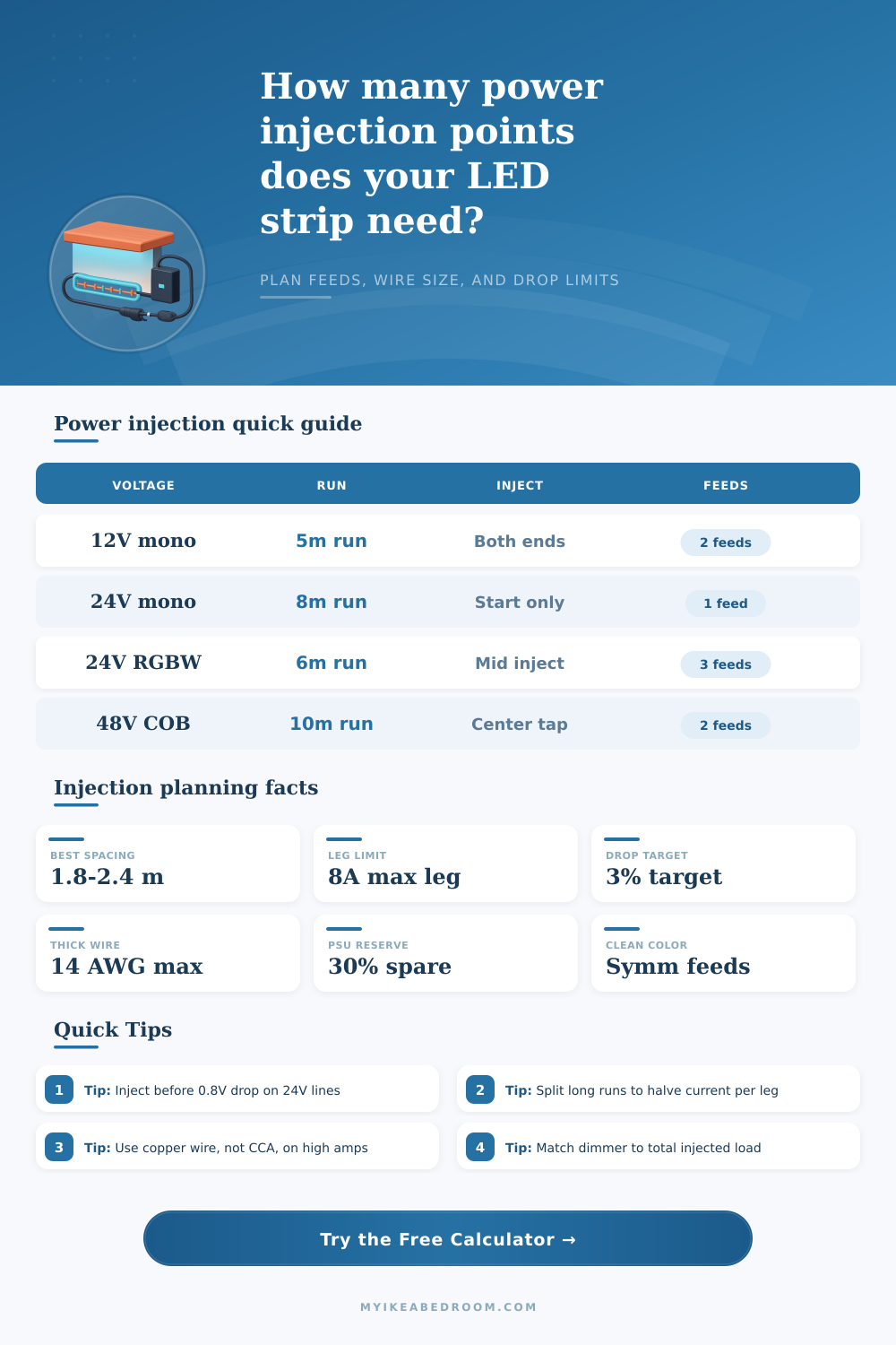
Additionally, you should limit the current per power feed to no more than 8 amp. There are different ways of feeding power to LED strips. One method is referred to as a single end feed, which is where the power is supplied to one end of the strip.
This method is only suitable for LED strips that is 10 feet or shorter in length. A both-ends feed supplies power to both ends of the strip, which divides the power requirement between both ends of the strip. A midpoint feed supplies power to the middle of the strip as well as each of its end.
Finally, a multi-zone power feed supplies power to many different points along the strip, which is useful for long strips or those that is installed in coves or loops. The material of the wires used to perform power injection is also important. Copper wire should be used, as it has less resistance then copper-clad aluminum (CCA) wire.
CCA wire has 50% more resistance than pure copper wire. Additionally, you should use thick copper wire; 14 AWG wire, for instance, can handle 6 to 8 amps over a 10-foot distance of LED strip. Any drop in voltage of 3% or less is recommended, as the human eye is unlikely to notice such a drop in brightness.
In addition to considering the type of LED strip that is to be powered, the wattage and voltage of the strips, and the type of power injection that is used, it is also important to provide some form of power reserve for the power supply unit (PSU). By providing a power reserve, the PSU will not have to work at its maximum capacity. For example, if the LED strip require 120 watts of power, a 150-watt PSU will work at around 85% of it’s capabilities.
By operating at 85%, the PSU will last longer before failing; operating at 100% can cause the PSU to overheat. Additionally, you should reserve 20% to 30% of the power supply in case of future changes to the LED lights or other devices, such as adding more LED strip or using a different dimmer. Finally, prior to installing the LED strips, they should be tested.
A voltmeter can be used to measure the voltage at the end of the LED strip while it is turned on. The voltage at the end of the strip can be used to determine whether or not the voltage drop is too great. If so, then additional power injection point should be installed into the strip, or the copper wire should be more thicker.
Adding more power injection points will reduce the amount of amps that pass through each part of the LED strip, which will allow the strip to remain cool to the touch.