Landscape Lighting Voltage Drop Calculator
Estimate voltage drop, end voltage, maximum run length, and wire gauge for low-voltage path lights, deck lights, uplights, driveway runs, and split branch layouts.
Choose a realistic run, then adjust voltage, wire, material, topology, branch count, and load until the farthest fixtures land in range.
End voltage: 12.00 V
Drop: 0.0%
End voltage: 12.00 V
Drop: 0.0%
End voltage: 12.00 V
Drop: 0.0%
End voltage: 12.00 V
Drop: 0.0%
| Wire gauge | Copper ohms per 1000 ft | Aluminum ohms per 1000 ft | Typical landscape use |
|---|---|---|---|
| 18 AWG | 6.385 | 10.47 | Very short low-load accent leads |
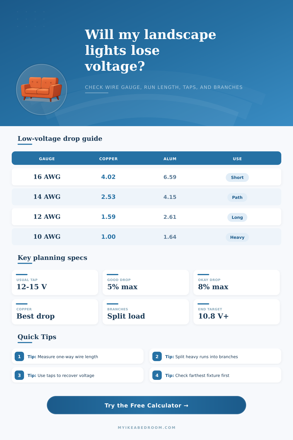
| 16 AWG | 4.016 | 6.59 | Short deck or step light branches |
| 14 AWG | 2.525 | 4.14 | Moderate path lighting runs |
| 12 AWG | 1.588 | 2.60 | Longer runs and higher wattage groups |
| 10 AWG | 0.999 | 1.64 | Long trunk feeds or heavy branches |
| 8 AWG | 0.628 | 1.03 | Very long low-voltage trunk runs |
| Load and length | 14 AWG | 12 AWG | 10 AWG |
|---|---|---|---|
| 24 W over 60 ft | 3.7% drop, 11.55 V | 2.3% drop, 11.72 V | 1.5% drop, 11.83 V |
| 36 W over 80 ft | 5.9% drop, 11.29 V | 3.7% drop, 11.56 V | 2.3% drop, 11.72 V |
| 60 W over 100 ft | 12.2% drop, 10.54 V | 7.7% drop, 11.08 V | 4.8% drop, 11.42 V |
| 90 W over 120 ft | 22.0% drop, 9.36 V | 13.8% drop, 10.34 V | 8.7% drop, 10.96 V |
| End voltage | Drop from 12 V | Planning status | Typical next move |
|---|---|---|---|
| 11.4 V to 12.0 V | 0% to 5% | Excellent | Keep layout or use smaller branches if desired |
| 11.0 V to 11.4 V | 5% to 8.3% | Usually workable | Check brightness at the farthest fixture |
| 10.5 V to 11.0 V | 8.3% to 12.5% | Borderline | Use larger wire, split the run, or raise tap |
| Below 10.5 V | Over 12.5% | Too low for many LED runs | Redesign with shorter or lower-current branches |
| Topology | Factor | Best use | Design note |
|---|---|---|---|
| All load near far end | 1.00 | Remote cluster | Most conservative drop estimate |
| Daisy chain | 0.58 | Path lights | Assumes fixtures are spread along the run |
| Center-fed | 0.50 | Two equal directions | Current travels a shorter average distance |
| Hub layout | 0.45 | Equal spokes | Works best when spokes are similar lengths |
| Loop feed | 0.35 | Closed loop path | Feed from both ends where equipment allows |
| Split branch | 0.65 | Two or more runs | Branch count still divides current |
Measure the electrical path. Use the one-way conductor distance from the transformer to the farthest fixture in that branch. The calculator doubles it internally for the outgoing and returning conductors.
Reduce current before raising voltage. Splitting a heavy run into branches, lowering fixture watts, or moving a transformer closer usually improves voltage balance more cleanly than relying on a high tap alone.
When you are planning your lighting layouts, you must consider the effect of voltage drops. Voltage drop is the decrease in voltage that occur as the voltage travels through the wire. The voltage drop that occurs in a wire is due to the resistance of the wire.
The resistance of the wire causes some of the electrical energy to be convert to heat rather than being delivered as light. Because the starting voltage of a low voltage lighting system is low, even an small voltage drop can result in the voltage at the end of the wire dropping to a level that the LED lights requires in order to emit light. If the voltage at the end of the wire is too low for the fixtures in use, then those fixtures will appear more dimmer than the other lights in the lighting layout.
How Voltage Drop Affects Low-Voltage Lighting
To assist with planning the lighting system to ensure that it will function proper, there are voltage drop calculators available. One of the parameters that you must enter into a voltage drop calculator is the one way length of the wire run from the transformer to the light fixtures. The voltage drop calculator does not require the total length of the wire runs, as it will automatically calculate the voltage drop for the return path of the electricity.
The other parameter is the load of the lights; the load can be entered in either total watts or total amp. The voltage drop calculator will automatically convert between watts and amps, so it isnt necessary to manually calculate the load in total amps. The topology of the lighting layout will also impact the voltage drop in the system.
For instance, layouts that use a daisy chain topology will have less voltage drop then layouts in which each light fixture is located at the end of the wire run. Similarly, designs that use a center fed or hub layout for the lights will have less voltage drop than designs using a daisy chain layout with the same total load. If the lighting layout contains branches of wire, it is also necessary to enter the branch count into the voltage drop calculator.
Voltage drop calculators will calculate the voltage drop for each branch of wire; the branch count allow the voltage drop calculator to calculate the voltage drop for each individual branch of wire. The material used to make the wire will also impact voltage drop. For instance, copper has less resistance than aluminum; therefore, wire made of copper will allow for less voltage drop than wire made of aluminum of the same size.
The voltage drop calculator allows for each lighting layout to be designed with either copper or aluminum wire; the calculator will automatically calculate the resistance of the wire based on the material select for the wire. The voltage drop calculator calculates three values. The first is the voltage drop in volts.
The second is the percent drop in voltage; this is the voltage drop expressed as a percentage of the starting voltage of the transformer. The third value is the voltage at the end of the wire; this is the remaining voltage after the voltage drop. The voltage at the end of the wire should be compared to the minimum voltage that is required by the LED lights to function; if the voltage at the end of the wire is too low relative to the voltage requirements of the lights, you can increase the size of the wire, shorten the length of the wire, or increase the starting voltage by using a higher tap on the transformer.
When calculating the voltage drop for a lighting system, it is important to also plan for a margin of error. For instance, the voltage drop may be slightly higher due to the soil temperature around the lights; loose connections in the lighting system will also allow for more voltage drop. Finally, it is possible to add more lights after the initial installation of the lighting system; additional lights will increase the load on the circuit.
Many designers plan for a maximum voltage drop of eight percent in their lighting design; however, many designers aim for a maximum voltage drop of five percent when they want all of the the lights in the lighting system to have the same brightness. Another consideration when lighting design is the future expansions of the lighting system. If it is important to be able to add lights in the future, it is best to install wire of a larger gauge than may be required at the initial installation; this will prevent the need to replace the wire if additional lights are to be added.
Finally, moving the transformer to a location closer to the lights that are to be controlled will also reduce the voltage drop in the system. These scenarios can be test in the voltage drop calculator by manually adjusting the length of the wire run or the branch count. Some of the mistakes that can be made when calculating voltage drop include entering the wrong distance to the fixtures or the wrong load.
For instance, if the round trip distance to the lights is entered rather than just the one way length of the wire from the transformer to the lights, the voltage drop calculations will not be accurate. Another mistake is treating each light fixture as if it is locate at the end of the wire rather than calculating the voltage drop for each distributed load of lights along the wire run; treating each light as if it is at the end of the wire will produce inaccurate calculations of the voltage drop. You can use the reference tables provided with many voltage drop calculators to verify the calculations that were performed in the system.
The reference tables provide information about how different gauge of wire will drop in voltage relative to the length of the wire and the load of the lights. These tables allow the designer to ensure that the voltage drop calculator calculations are accurate. Finally, the goal of the voltage drop calculator is to ensure that each light fixture in the system receives enough voltage to provide the planned level of light.