Junction Box Fill Calculator
Count conductors, device yokes, internal clamps, grounding conductors, and box volume to estimate whether a junction box meets NEC-style cubic inch fill rules.
Choose a common box setup to load realistic starting counts. Always use the volume marked on the actual box when it differs from a reference size.
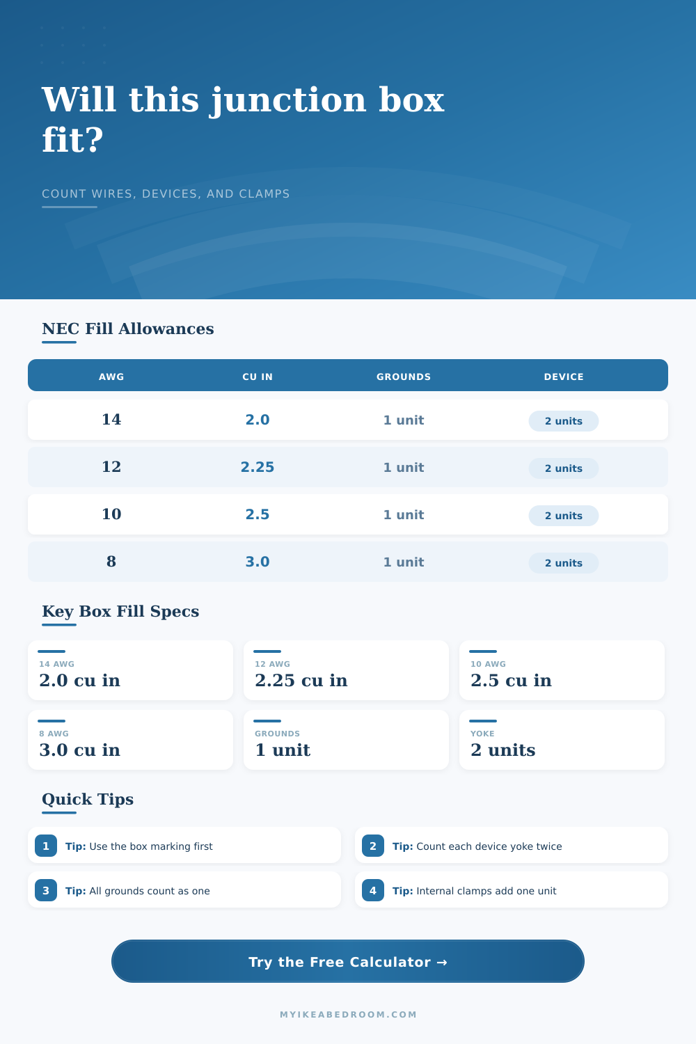
| Conductor size | Volume allowance | Metric volume | Typical use note |
|---|---|---|---|
| 18 AWG | 1.50 cu in | 24.6 cm3 | Low-voltage or control conductors where applicable |
| 16 AWG | 1.75 cu in | 28.7 cm3 | Control conductors where applicable |
| 14 AWG | 2.00 cu in | 32.8 cm3 | Common 15 A copper branch circuits |
| 12 AWG | 2.25 cu in | 36.9 cm3 | Common 20 A copper branch circuits |
| 10 AWG | 2.50 cu in | 41.0 cm3 | Larger branch-circuit conductors |
| 8 AWG | 3.00 cu in | 49.2 cm3 | Large junction or feeder work |
| 6 AWG | 5.00 cu in | 82.0 cm3 | Large feeder conductors |
| Box reference | Reference volume | Best use in calculator | Important check |
|---|---|---|---|
| 1-gang shallow device box | 12.5 cu in | Very light switch counts | Usually tight with devices and clamps |
| 1-gang standard device box | 18.0 cu in | Simple receptacle or switch | Watch 12 AWG device fill |
| 1-gang deep device box | 22.5 cu in | One device with more conductors | Check molded volume marking |
| 2-gang standard device box | 32.0 cu in | Two yokes with moderate wiring | Device yokes add four allowances |
| 2-gang deep device box | 42.0 cu in | Two devices plus travelers | Often safer for crowded switches |
| 4 in square, 1-1/2 in deep | 21.0 cu in | Small splice junction | Raised covers can add listed volume |
| 4 in square, 2-1/8 in deep | 30.3 cu in | Deeper splice junction | Use actual listed steel box volume |
| 4-11/16 square, 1-1/2 in deep | 29.5 cu in | Larger junction space | Good for multiple cable entries |
| 4-11/16 square, 2-1/8 in deep | 42.0 cu in | Dense junction or feeder splice | Confirm cover and ring markings |
| 3-gang deep plastic box | 55.5 cu in | Grouped switch or receptacle devices | Internal clamps may be molded in |
| Item in the box | How this calculator counts it | Multiplier | Planning note |
|---|---|---|---|
| Insulated conductors | Each counted conductor uses the selected AWG allowance | 1 per conductor | Count conductors entering and terminating or spliced in the box |
| Device yokes or straps | Each yoke uses two allowances based on largest conductor | 2 per yoke | A duplex receptacle on one yoke counts as one yoke |
| Equipment grounding conductors | Grounding conductors together use one allowance here | 1 total | Base the allowance on the largest grounding conductor |
| Internal cable clamps | All internal clamps together add one allowance | 1 total | External cable connectors usually do not add volume |
| Fixture studs or support fittings | Support fittings add one allowance when present | 1 total | Use when a fitting occupies internal box space |
| Short pigtails | Not entered as extra counted conductors | 0 here | Pigtails originating and ending in the same box are usually excluded |
When you put more than will fit in the electrical box, which looks like a crumpled up soda can; it’s not only bad looking. It’s also dangerous.
The National Electrical Code contains regulations for what you can cram into a junction box, but they’re expressed in abstract terms: cubic inches and allowances. The calculator above handles those calculations for you, so they aren’t so abstract when you pick up pair of wire strippers. The calculator do the math for you. It takes your real-world configuration of wire and turns it into numbers that matter to code inspectors. It sounds pretty basic in principle, but there are ways to screw this one up.
Why You Should Not Overfill Electrical Boxes
For starters, everything in the box occupy some volume. That volume has to be accounted for. It is obvious that the insulated conductor take up room. If it enters the box, ends or splices, each one adds one. People get confused by what is not visible. The yoke of a receptacle or switch are two conductors. This makes sense because the hardware itself occupies space, but this can confuse some people during rough-in time. Internal cable clamps add one unit for all of them. Grounding conductors grouped together counts as one even if they are multiple ground wires. Not a big deal, but it will matter if you are cutting it close.
The other thing is you should selects the biggest conductor size from among the mix. For example, if you’ve got both a 14 AWG control wire and a 12 AWG feeder, then the whole calculation will default to larger 12 AWG’s volume allowance. Larger conductors requires more space. This is where the tool uses the standard NEC table values. It allows two cubic inches for a 14 AWG wire. Three for an 8 AWG. On paper, that doesn’t seem like much of a difference, but when you’re cramming six wires (plus the device!) into a standard single-gang box, it matters.
Based off that maximum-sized wire, the calculator will multiply that amount by how many units you’ve entered.
These are common box sizes. Electricians use presets and standard box sizes often. An average single-gang device box will generally provide eighteen cubic inches. A deep one may be as high as twenty-two and a half. Square boxes differs in manufacturer and depth. Always seek out the molded volume number found on the interior of the box. It’s the law. Whatever number it reads, that’s what you’ve got to work with. If the box says eighteen cubic inches, that is your limit. The box claims fifteen, well, now you’re operating with smaller margins then expected. Being able to enter your own measurements instead of using preset volumes is key when dealing with old, specialty, or metal boxes that don’t follow today’s standards.
It will tell you if it passes or fails. And if it doesn’t it will also show you what capacity you was lacking compared to what you had. Even better, it will also give you an idea of your remaining spare capacity. If it’s negative, then you either need a dome extension ring or larger box. You can’t just jam the wires in there. There are real concerns with heat dissipation and mechanical strain on the components inside the box.
Typically the pigtails that originate and end in the same box are not counted towards the fill. This lets you handle complex splices without bloating up your fill count unnecesarily. As long as the pigtailed connections is neat and secure
In theory, a spreadsheet looks nice, but this isn’t the real world. In the real world you have to install things like THHN wire, make tight bends, and work in small spaces. Sometimes a box may mathematically pass the fill test, but it’s so tight that it’s difficult to work inside of. Deeper boxes gives you additional height for your wire folds. Not only does this reduce termination strain, but it will simplify future maintenance as well. Do you really want to go fishing for wires inside a full box in five years? No, we’re trying to create breathing room here.
Inspect your clamps. Mains entry typically doesn’t count towards fill. Molded-in, inside clamps do. Many DIYers get tripped up on this, assuming all their cable entries are free. The tool requests that you indicate this. Honesty is the best policy here. The math will tell you the truth.
Add an extra unit of safety margin if you’re near capacity. Buying a deeper box is cheaper than rewiring later. Feed the calculator with accurate counts and it’ll run the math for you (see link above).
Organize your wires. Follow the volume limits. Your box will last longer. You’ll pass inspection. And you won’t be facing down a crumpled-cable disaster, just one you could of told as a story.