Flashing Length Calculator
Estimate flashing length for roof edges, valleys, step flashing, chimneys, deck ledgers, parapets, and window heads or sill pans using measured runs, repeated sections, lap loss, corner allowances, end returns, and stock lengths.
Each preset loads a real roof, wall, or window flashing detail with a typical material, lap rule, returns, deductions, and waste allowance. Adjust the measured values after loading.
Flashing length estimate
| Flashing detail | Planning lap | Return allowance | Common overage |
|---|---|---|---|
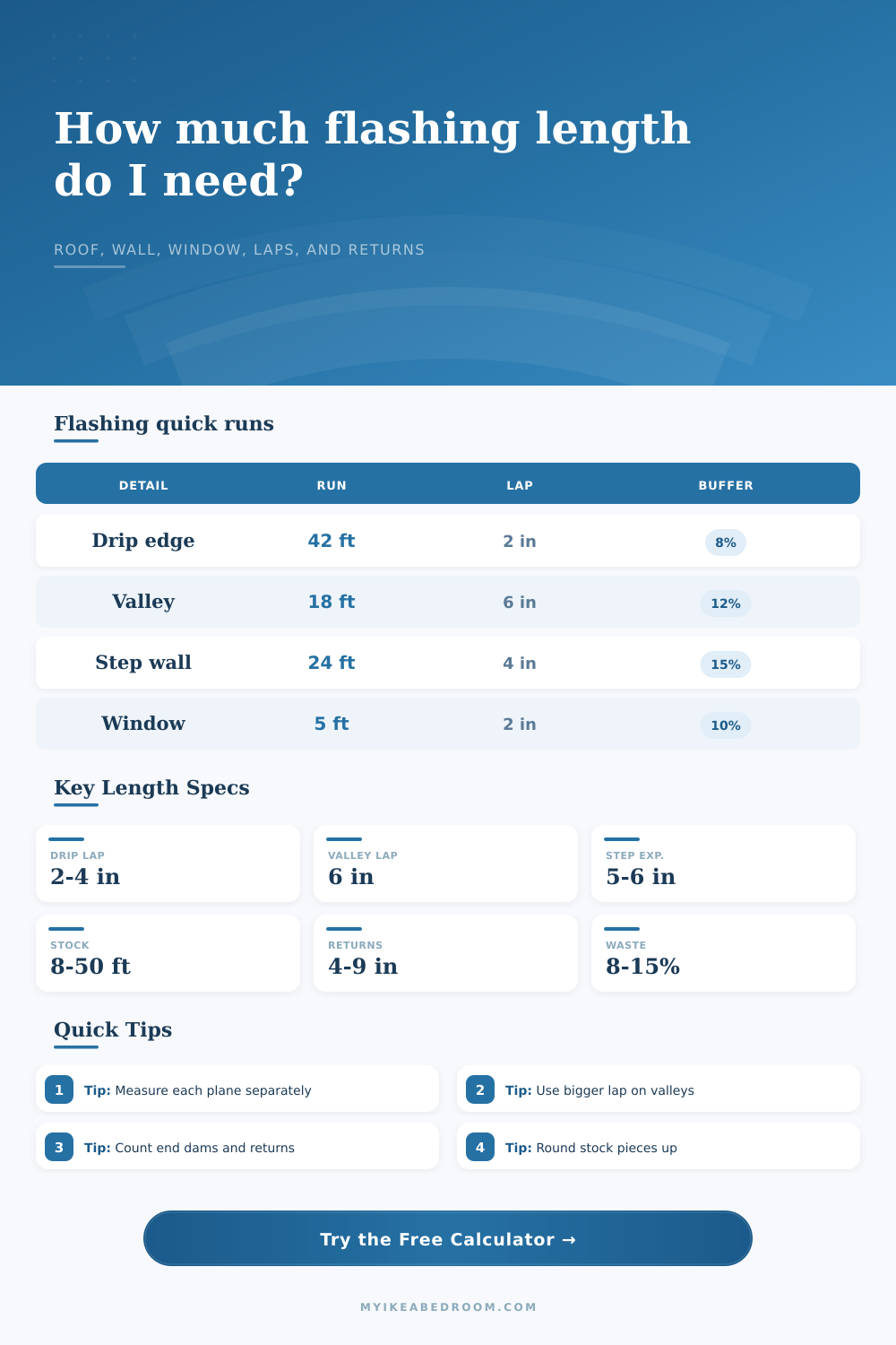
| Drip edge or rake edge | 2 to 4 in end laps | About 6 in at roof ends | 5 to 8 percent |
| Open valley metal | 6 in end laps, more on low slope | About 9 in at ridge or eave turns | 10 to 12 percent |
| Step flashing along sidewall | One step per shingle course | About 6 in at kickout or stop ends | 12 to 15 percent |
| Window head cap | 2 in minimum end lap or shingle lap | About 6 in side extensions | 8 to 10 percent |
| Sill pan or flexible membrane | 3 in minimum membrane lap | 4 to 8 in turned-up end dams | 10 to 12 percent |
| Chimney counterflashing | 4 to 6 in laps at reglets or seams | About 9 in at corners and overlaps | 12 to 15 percent |
| Formula item | Calculation | Why it matters | Output affected |
|---|---|---|---|
| Straight run | (Measured run - deductions) x repeated runs | Removes skylight, doorway, or interrupted sections | Base length |
| Corner allowance | Corners x assembly corner adder | Adds length for miters, folds, wraps, and plane changes | Net length |
| Return allowance | Returns x assembly return depth | Adds end dams, upturns, kickouts, and side returns | Net length |
| Lap loss | Joints x selected lap length | Overlapped stock does not add full visible coverage | Piece count |
| Piece count | Ceiling((needed - lap) / (stock - lap)) | Rounds up to stock pieces with lap loss included | Order quantity |
| Stock format | Piece length | Lap used | Coverage from 3 pieces |
|---|---|---|---|
| Rigid metal stick | 10 ft | 4 in | 29.33 ft installed |
| Short custom pan | 8 ft | 4 in | 23.33 ft installed |
| Membrane roll | 33 ft | 3 in | 98.5 ft installed |
| Aluminum trim coil | 50 ft | 4 in | 149.33 ft installed |
| Wall run | 5 in exposure | 5.5 in exposure | 6 in exposure |
|---|---|---|---|
| 8 ft sidewall | 20 step pieces | 18 step pieces | 16 step pieces |
| 12 ft sidewall | 29 step pieces | 27 step pieces | 24 step pieces |
| 18 ft sidewall | 44 step pieces | 40 step pieces | 36 step pieces |
| 24 ft sidewall | 58 step pieces | 53 step pieces | 48 step pieces |
Roof edge runs
Best input: measure each eave and rake separately, then use repeated runs for matching sides.
Deduct only true gaps where flashing stops.
Valleys
Best input: measure from eave to ridge along the valley centerline.
Use larger lap and overage because cuts are diagonal.
Windows
Best input: measure rough opening width plus side returns or end dams.
Head caps and sill pans often need different return counts.
Chimneys
Best input: total all four sides before adding corners and reglet laps.
Use the corner count to account for wrapped bends.
Measure by detail, not by material. A single roof plane may need drip edge, valley, apron, and step flashing. Calculate each flashing type separately so lap rules and returns stay accurate.
Use the stock piece result as the round-up point. The calculator applies laps before rounding stock pieces, so a 10 ft stick does not provide 10 ft of installed coverage after overlaps.
Most roof leaks occur at a seam where flashing has failed to do its job; water enters through the weakest part of the seam. A single shingle might blow off in a windstorm, but water behind that flashing will rot out interior sheathing. It’s not visible until it’s too late and damage gets serious, which makes exact measurements more important then cutting corners by ordering extra length and hoping you get lucky.
The other reason flashing isn’t linear tape is because there is joints that overlap each other. Two 10 foot lengths of aluminum side by side don’t equal 20 feet long; some of the length gets covered in the overlap. So the combined length are actualy shorter than sum of individual lengths. Fail to account for this and you will be out of material halfway up a chimney. But knowing how it’s calculated would of save you from expensive errors on site.
How to Measure Roof Flashing
There is also a common length of most metal flashing available: it comes as a coil or in standard lengths, usually 10 feet for copper and steel. For aluminum drip edge, 50 foot rolls are typical, and the tool pulls up a default lap size based off your assembly type. For instance, a six inch overlap is needed on a valley to shed water correctly; two inches might be all right for a simple drip edge. So keep that in mind ahead of time, because it will greatly affect how many pieces you has to cut.
It’s hard to eyeball returns and corners because they don’t appear in the linear measurement. For example: you can measure a 12 foot wall but the metal will have to either kick out or turn up at each end. The calculator accounts for those turns. This ensures your pieces aren’t hanging loose and tight wrap looks better than a gap.
Because each step need to overlap the one below it by about five inches to match shingle exposure, you can’t simply measure linear feet but must instead count number of courses required; then multiply by amount of material needed per course: An 8-foot wall with a 5-inch exposure requires approximately twenty pieces of material (since each step need to overlap by about five inches), and if you don’t add that into the equation, you’ll be heading back to the ladder for another piece or two while your hands are otherwise occupied. Pre-planning saves time!
Copper comes in shorter sheets that will have more laps and therefore more waste; stainless steel tends to be offered in 8-foot lengths and is inflexible around a corner (though this mean fewer joints). Membranes, flexible though they are on an irregular surface, should has a minimum lap of three inches; diagonals create more scrap, so valleys receive a larger waste allowance. On straight runs where cutting is easier, you’ll recieve a lower allowance.
Measure individual planes instead of guessing at the entire roof, because valleys and gable ends require different flashing. Breaking it down into specific runs makes sense; that way the math is do-able and you can also picture where laps will occur. Staggering the joints improves durability and prevents water from running directly down a seam.
Metal will flex into corners, cuts won’t be exact, and there’s no accounting for all the other things that happens in the real world. Adding an extra 8-15% (depending how complicated it is) allows for real-world variables as well, since fasteners can throw things off center when you’re installing them. Better to have some excess material than run out while waiting for a delivery truck.
The good news is, if you cut them exactly to size, they’ll seal forever.