Underfloor Heating Pipe Spacing Calculator
Estimate UFH pipe spacing, total pipe length, edge and field zone split, loop count, heat output, and a practical pressure-risk proxy from room load, floor type, pipe size, and temperature.
Presets load realistic room area, heat load, pipe diameter, supply temperature, floor finish, edge zone, target spacing, and loop length assumptions. Adjust any field for the actual design.
Calculation breakdown
12 mm retrofit pipe
Best use: low-build overlay boards and small rooms.
Spacing: 100 to 150 mm is common because smaller pipe carries less water.
Risk: pressure rises quickly on long loops, so shorter circuits are usually sensible.
16 mm standard pipe
Best use: most screed, slab, and panel UFH systems.
Spacing: 100 to 200 mm covers many residential rooms.
Risk: balanced loops around 70 to 90 m usually remain manageable.
20 mm slab pipe
Best use: large areas and thicker slabs where wider spacing is acceptable.
Spacing: 150 to 250 mm can work when loads are moderate.
Risk: longer loops are possible, but response time is slower.
Floor resistance
Tile/slab: strong output with lower water temperature.
Wood/carpet: needs careful temperature limits and closer spacing.
Overlay: responds faster but may need shorter loops.
| Spacing | Approx pipe per m2 | Approx pipe per 100 sq ft | Typical use |
|---|---|---|---|
| 75 mm / 3.0 in | 13.3 m per m2 | 436 ft per 100 sq ft | Cold perimeter or wet room edge band |
| 100 mm / 3.9 in | 10.0 m per m2 | 328 ft per 100 sq ft | High output field spacing |
| 150 mm / 5.9 in | 6.7 m per m2 | 219 ft per 100 sq ft | Standard insulated room field |
| 200 mm / 7.9 in | 5.0 m per m2 | 164 ft per 100 sq ft | Low load bedroom or hallway |
| 250 mm / 9.8 in | 4.0 m per m2 | 131 ft per 100 sq ft | Very low load slab area |
| Floor type | Output factor | Useful supply range | Design note |
|---|---|---|---|
| Tile or stone over screed | 1.12 | 35 to 45 C | Low resistance finish gives the strongest surface output. |
| Polished concrete or slab | 1.04 | 35 to 45 C | Stable output, higher thermal mass, slower response. |
| Thin vinyl or laminate | 0.96 | 32 to 42 C | Check product temperature limits before increasing water temperature. |
| Engineered wood | 0.82 | 30 to 40 C | Keep surface temperature within the flooring supplier limit. |
| Carpet and underlay | 0.68 | 35 to 45 C | Low tog assemblies perform much better than thick carpet stacks. |
| Timber joist plates | 0.74 | 38 to 48 C | Spreader plates help, but output is usually below screed. |
| Retrofit overlay board | 0.88 | 32 to 43 C | Fast response, but pipe channels often limit spacing choices. |
| Average loop length | 12 mm pipe | 16 mm pipe | 20 mm pipe |
|---|---|---|---|
| Under 50 m / 165 ft | Medium risk | Low risk | Low risk |
| 50 to 70 m / 165 to 230 ft | High risk | Low to medium risk | Low risk |
| 70 to 90 m / 230 to 295 ft | Very high risk | Medium risk | Low to medium risk |
| 90 to 110 m / 295 to 360 ft | Very high risk | High risk | Medium risk |
| Scenario | Area | Load | Starting spacing |
|---|---|---|---|
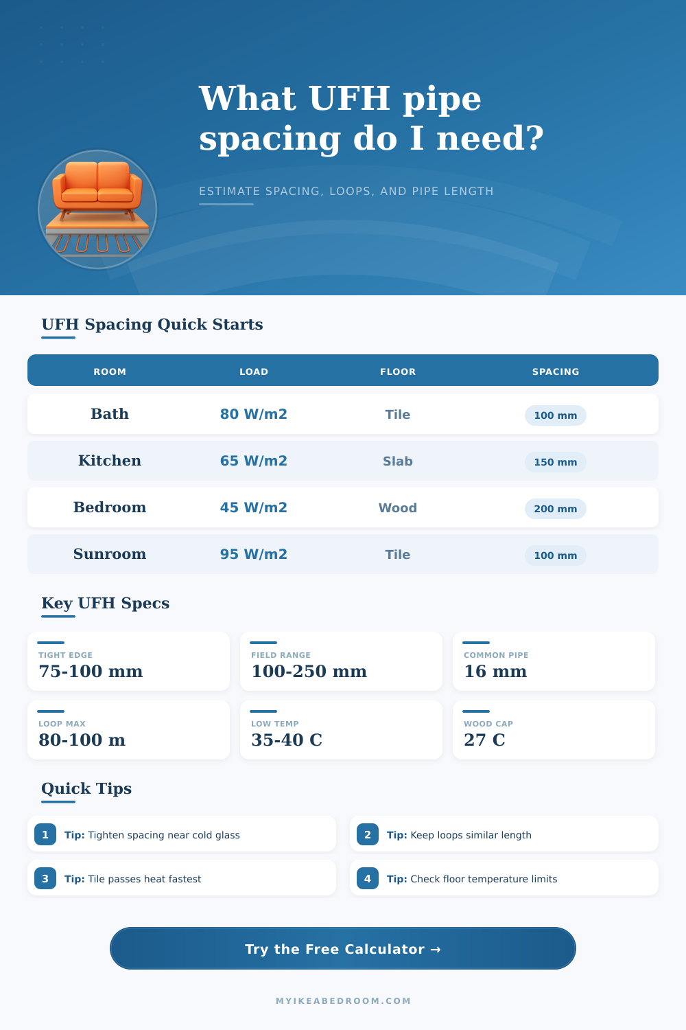
| Bathroom tile floor | 8.5 m2 | 80 W/m2 | 100 mm with 75 mm edge band |
| Kitchen slab | 18 m2 | 65 W/m2 | 150 mm with standard loop lengths |
| Bedroom retrofit | 13 m2 | 45 W/m2 | 200 mm with overlay board |
| Conservatory glazing | 14 m2 | 95 W/m2 | 100 mm with wide edge zone |
| Low temp heat pump | 22 m2 | 55 W/m2 | 100 mm to improve low water output |
Edge zones: Use the edge zone for the colder strip near external walls and glazing, not the entire room. The calculator tightens that strip while keeping the field spacing separate.
Loop balance: Similar loop lengths make balancing easier at the manifold. If the average loop is near the limit, split into one extra loop instead of stretching a circuit.
When ordering your underfloor heating pipe, there’s always that moment of anxiety. You’ve measured out the room and picked your tiles. Now you need to decide how far apart you want them spaced. Will a hundred millimeters be sufficient? Or will you end up shivering in your jumper with a faint warm breeze on your face? The calculator do the maths for you, and spares you having to design a system which can’t cope with January (or buying too much pipe!). But understanding what is being calculated save you from mistakes, so there are no surprises.
The number of pipes isn’t just a measure of how much floor space it covers: There’s a tradeoff between pressure and output. More pipe = more surface area touching the slab (or screed), which translates into quicker loss of heat. Sounds nice on the comfort bill…until you remember that more pipe also equals greater hydraulic resistance. Pack them in too tightly over a large area, and all that pipe resists your pump’s attempts to push water through the loops; you get uneven heating as the beginning of each loop gets hot while the end barely feels warmed. The tool looks at the pipe diameter in relation to the loop length you want to create, and estimates your risk of creating uneven pressure. Before laying a single coil, it’ll tell you whether you’re pushing the system too hard.
How to Plan Your Underfloor Heating Pipes
The other thing that makes a difference in all this is the type of floor: The floor finish. Why does the floor type matter so much? Some types conducts the heat, like tile or stone laid over screed, while others do not such as wood. Because tile or stone help spread the heat, you can space them further apart. On the flip side, solid wood expands and contracts based off temperature differences. To prevent warping or gaps, you have to reduce the surface temperature. But since less heat is being released per square meter of floor, you’ll often have to tighten up your piping spacing to achieve the same room temperature. If you fail to account for this sort of thermal resistance, you’re likely to end up underheating the room, no matter how hot the water gets in the pipes.
Most amateur installations fails in one simple way: They fail to account for edge zones. Even when the thermostats are happy, the cold air dropping down external walls and windows creates a thermal draft that makes the middle of the room feel chilly. To stop this draft in its tracks, smart designs employ tighter pipe spacing around those cold edges to form a warm curtain of air between you and the cold. The calculator divides the space into two zones, the field and an edge band. It automatically tightens the spacing around the walls but keeps wider spacing across the rest of the room to balance loop length needs. A dual-density approach like this is much more efficient then running the entire room at max density, which wastes pipe and needlessly raises pump load.
Another silent killer of underfloor heating performance: loop length. For example, when renovating a large open-plan room, it’s tempting to run just one big circuit (fewer manifold ports), which seems cheaper until you switch it on. Long runs translate to large pressure drop between the supply and the return side of the loop, causing bad flow balance and temperature stratification (hot and cold patches) along the floor. Depending on pipe size, risk increases with length; see the reference tables on the page. While a 16 mm pipe may be OK up to eighty meters, stretch it past ninety or a hundred and you’re bucking physics. Two balanced loops split up the space. This could of feel like a more painful installation, but it pays off right away in terms of control and comfort.
Underfloor heating is all about balance. There’s no need to pack the floor with pipe to get it warm. You just need the right amount, placed at the correct distance for your floor type, in sensible loop lengths so there’s actualy water circulation. The numbers produced by this tool help you plan. They can helps you visualise the trade-off between output and length and spacing before laying tiles/screeding the floor, pointing you towards a viable design. As soon as you understand how these variables interact, the anxiety fades, replaced by a feeling that stops wondering if it’ll work and starts creating a system that knows precisely what to do. That sense of control is priceless, beyond any individual number on the screen.