Microfarad estimate, voltage rating check, and tap split planning for ceiling fans
Ceiling Fan Capacitor Value Calculator
Estimate a practical run-capacitor microfarad range, safer VAC rating, and common single or dual replacement layout from room size, blade span, voltage, motor watts, current draw, and target speed tap.
Each preset changes room size, fan span, line voltage, running load, power factor, and capacitor style so you can compare common bedroom and suite setups instead of starting from a blank form.
Results stay below this input block on purpose. Use the room fields for fan class context, then fine-tune the electrical numbers from your label, clamp meter, or existing capacitor marking.
| Blade span | Typical watts | Common capacitor range | Most common use |
|---|---|---|---|
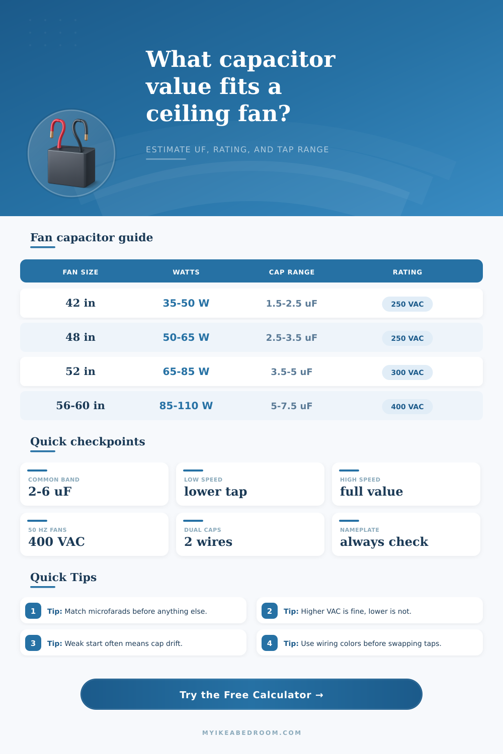
| 36 to 42 in | 30 to 50 W | 1.5 to 2.5 uF | Nursery, office, compact guest room |
| 44 to 48 in | 45 to 65 W | 2.5 to 3.5 uF | Standard bedroom and small porch room |
| 52 in | 60 to 85 W | 3.5 to 5.0 uF | Most primary bedrooms and balanced suites |
| 56 to 60 in | 85 to 110 W | 5.0 to 7.5 uF | Large rooms, lofts, high-airflow layouts |
| Fan electrical setup | Minimum rating | Better shelf pick | Why it helps |
|---|---|---|---|
| 110 to 120 V, 60 Hz, under 4.5 uF | 250 VAC | 300 VAC | Handles typical bedroom fan service cleanly |
| 120 V, 60 Hz, 5 to 6 uF | 300 VAC | 350 VAC | Useful when the motor runs warm or enclosed |
| 220 to 240 V, 50 or 60 Hz | 400 VAC | 450 VAC | Common export ceiling fan replacement practice |
| Unreadable old part, mixed conditions | Match label | Next higher VAC | VAC headroom is safer than underspec parts |
| Style | Common printed marking | What the fan uses it for | Replacement note |
|---|---|---|---|
| Single value | 4.0 uF | One main run value for a simple motor circuit | Closest exact match is usually best |
| Dual value | 2.5 + 3.0 uF | Separate taps for high and lower speed behavior | Keep every wire on the same color lead |
| Three value | 1.5 + 2.0 + 3.5 uF | Multi-speed control in legacy pull-chain fans | Photograph the old part before disconnecting |
| Combo shell | 4 wire fan cap | Bundles several values into one compact housing | Match both value and wire order |
| Symptom | Likely capacitor issue | Direction to check | Fast sanity test |
|---|---|---|---|
| Hum with weak start | Capacitance drifted low | Check one step up toward the printed value | Spin blade by hand after power is off |
| Runs but never reaches full speed | Too little effective capacitance on high tap | Verify the high-speed wire is on the full value | Compare with old wire colors |
| Too fast or noisy after repair | Replacement value may be too large | Step back toward the original printed number | Measure line current and housing heat |
| New part fails early | VAC rating too low for service | Move to a higher VAC replacement | Check voltage and frequency nameplate |
A capacitor is an small component that is contained within the housing of a ceiling fan. The function of the capacitor are to create a phase shift in the motor’s power supply that allows the motor to spin smooth. Many ceiling fans experiences issues due to the fact that the capacitor for those fans can fail due to its age or the heat that the fan itself creates.
When a ceiling fan capacitor begins to fail, the fan may spin slow when it should spin at a normal rate, or it may not start at all. Often, fans that exhibit these failing characteristics will hum but the blades will not rotate, a sign that the capacitance provided by the capacitor is too low. The capacitance value of a capacitor for a ceiling fan must be chose carefuly.
What a Ceiling Fan Capacitor Does and How to Test It
If the capacitance value of the capacitor that is installed is too low, the motor will struggle to start, and the motor will create excess current. Too high of a capacitance value will lead to the motor spinning at a faster rate then it should exhibit it’s noisiness may increase, and the stress on the motor bearings will increase. The correct capacitance value will depend on a variety of factors regarding the fan itself, such as the blade span, the room dimensions, and the motor power draw.
Several factors will impact the capacitance value of the capacitor for a ceiling fan. Factors like the blade span of the fan will impact the capacitance value. For example, fans with forty-two inch blade spans has capacitance values between one and a half and two and a half microfarads, but fans with sixty inch blade spans may require capacitance values between five and seven and a half microfarads.
Additional factors include the size of the rooms in which the fans are located. The larger the rooms and the ceilings in those rooms, the more capacitance will be required to move an air within the rooms. Finally, the wattage of the motors will impact the capacitance value of the fans.
Fans with eighty-five watts of motor power may require a different capacitance than fans with motors that use only thirty watt of power. Another factor that will impact the selection of a capacitor for a ceiling fan is its voltage ratings. The voltage ratings of the new capacitor must be equal to or higher than that of the original capacitor for that fan.
If they are too low, the capacitor will fail. For example, if a ceiling fan is used in a standard 110 volt system, a capacitor with a 300 volt rating should be used. In the case of 50 hertz systems, however, a rating of 400 volts should be used since the lower voltage and frequency in those systems place additional stress on the capacitor.
Many moddern ceiling fans use a type of capacitor referred to as a multi-value capacitor. These types of capacitors contains more than one value of capacitance within the same housing. These different capacitance values control the different speeds that a ceiling fan can exhibit.
Each speed that the fan can exhibit is connected to a specific capacitance value within that housing of the multi-value capacitor. Each capacitance value is color-coded. Thus, it is important to match the colors of the wires of the new, replacement, multi-value capacitor with the colors of the wires of the old, failing capacitor.
Taking a photograph of the old capacitor before disconnecting it from the fan will assist in setting the replacement capacitor to the same value as the failing capacitor. A faulty ceiling fan capacitor can be diagnosed by observing the fan while it is in operation. For instance, if the fan motors require the blades to be pushed to start the motor, the capacitor has likely failed.
If the fan motors tend to reach a top speed that is less than that of the original fan, the capacitance provided by the capacitor may be too low. Additionally, using a clamp meter to measure the amount of current that the motor draws will exhibit high readings if the capacitor is failing. Finally, spinning the fan blades by hand while the fan is off will test the bearings for the fan.
If the motor blades spin easy by hand, the bearings are likely functioning properly and the capacitor is the issue.